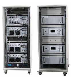
Complies with ISO 11452-2 and GB 33014.2 requirements
Operating Frequency: 80 MHz – 6 GHz
Output Power: 250 W – 2000 W
Input VSWR: ≤2.0
Output VSWR: 2.0 – 4.5
AC Operating Voltage: 198 V–240 V, 340 V–530 V
Operating Temperature: 0 ℃ – 40 ℃
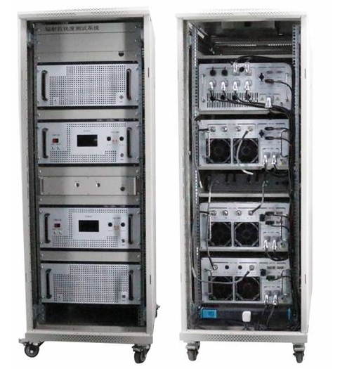
Full Series of ISO 11452-2 Power Amplifiers
Suitable for automotive electronic field strength testing
User-friendly human-machine interface
Rational design with elegant appearance
Reliable quality and easy operation
Professional EMC Power Amplifier Solutions
|
|
I. Power Amplifier Series Models
|
|
Model
|
Frequency
MHz
|
Output Power
Min
(Past)
dBm
|
Output Power
Typ(P-1)
dBm
|
Gain
Min
dB
|
Flatness
Typ
dB
|
Output VSWR
Typ
|
Input VSWR
Typ
|
Dimension
L*W*Hmm*mm*mm
|
|
ZLPA80M1G1000
|
80-200
|
60.0
|
57.0
|
60.0
|
±2.0
|
5.0
|
2.0
|
480*550*1100
|
|
200-1000
|
57.0
|
54.0
|
57.0
|
±3.0
|
5.0
|
2.0
|
|
ZLPA1G6G200
|
1000-6000
|
53.0
|
50.0
|
53.0
|
±4.5
|
4.0
|
2.0
|
480*550*225
|
|
ZLSPDTDC6G2000-3
|
80-6000
|
63.0
|
---
|
---
|
±1.0
|
---
|
2.0
|
480*550*225
|
|
|
|
|
II.Technical Specifications
|
|
|
|
1、Model:LDPA80M1G1000/500
|
|
|
|
Operating Specifications(Technical Specifications
|
|
Parameter(Parameters)
|
Min
|
Typ
|
Max
|
Units(单位)
|
|
Frequency(Frequency)
|
80.0
|
---
|
200.0
|
MHz
|
|
200.0
|
---
|
1000.0
|
|
Avg Output PowerPast(Output Saturation Power)
|
1000.0
|
---
|
---
|
Watts
|
|
500.0
|
---
|
---
|
|
Avg Output Power P-1(Output Linear Power)
|
500.0
|
---
|
---
|
Watts
|
|
400.0
|
---
|
---
|
|
Gain(Gain)
|
60.0
|
---
|
---
|
dB
|
|
57.0
|
---
|
---
|
|
Power In(Input Power)
|
---
|
---
|
3
|
dBm
|
|
Supply Voltage(Supply Voltage AC)
|
340
|
---
|
530
|
V
|
|
Supply Power(Supply Power AC)
|
---
|
---
|
10000
|
W
|
|
Gain Flatness(Gain Flatnes)
|
---
|
±4.0
|
---
|
dB
|
|
Harmonic(Second Harmonic)@P1dB
|
---
|
-20
|
---
|
dBc
|
|
Spurious(Spurious)
|
---
|
-50
|
---
|
dBc
|
|
Storage Temp(Storage Temperature)
|
-20
|
---
|
60
|
℃
|
|
Case Oper Temp(Operation Temperature)
|
0
|
---
|
40
|
℃
|
|
Input VSWR(Input VSWR)
|
---
|
2.0
|
---
|
|
|
Output VSWR(Output VSWR)
|
---
|
5.0
|
---
|
|
|
Nominal impedance(Nominal Impedance)
|
---
|
50
|
---
|
Ω
|
|
Amplifier Safeguard Temp(Power Amplifier Temperature Protection)
|
60
|
---
|
---
|
℃
|
|
Safeguard Power In(InputSignal Protection)
|
---
|
---
|
3
|
dBm
|
|
Connector(Connector)
|
RFin:N-F,RFout:7/16-F,FWD:N-F,RVE:N-F(Connector on the Rear Panel)
|
|
Dimension(Dimension)
|
25U19 inch Chassis Approximately(480×550×1100mm)
|
|
Control system(Control)
|
Ethernet Port/GPIB
|
|
Remarks(Remarks)
|
|
|
|
|
|
|
|
2、Model:LDPA1G6G200
|
|
|
|
Operating Specifications(Technical Specifications)
|
|
Parameter(Parameters)
|
Min
|
Typ
|
Max
|
Units(单位)
|
|
Frequency(Frequency)
|
1.0
|
---
|
6.0
|
GHz
|
|
Avg Output PowerPast(Output Saturation Power)
|
200.0
|
---
|
---
|
Watts
|
|
Avg Output Power P-1(Output Linear Power)
|
80.0
|
---
|
---
|
Watts
|
|
Gain(Gain)
|
53.0
|
---
|
---
|
dB
|
|
Power In(Input Power)
|
---
|
---
|
3
|
dBm
|
|
Supply Voltage(Supply Voltage AC)
|
198
|
---
|
240
|
V
|
|
Supply Power(Supply Power AC)
|
---
|
---
|
3200
|
W
|
|
Gain Flatness(Gain Flatnes)
|
---
|
±4.5
|
---
|
dB
|
|
Harmonic(Second Harmonic)@P1dB
|
---
|
-20
|
---
|
dBc
|
|
Spurious(Spurious)
|
---
|
-50
|
---
|
dBc
|
|
Storage Temp(Storage Temperature)
|
-20
|
---
|
60
|
℃
|
|
Case Oper Temp(Operation Temperature)
|
0
|
---
|
40
|
℃
|
|
Input VSWR(Input VSWR)
|
---
|
2.0
|
---
|
|
|
Output VSWR(Output VSWR)
|
---
|
4.0
|
---
|
|
|
Nominal impedance(Nominal Impedance)
|
---
|
50
|
---
|
Ω
|
|
Amplifier Safeguard Temp(Power Amplifier Temperature Protection)
|
60
|
---
|
---
|
℃
|
|
Safeguard Power In(InputSignal Protection)
|
---
|
---
|
3
|
dBm
|
|
Connector(Connector)
|
RFin:N-F,RFout:N-F,FWD:N-F,RVE:N-F(Connector on the Rear Panel)
|
|
Dimension(Dimension)
|
5U19 inch Chassis Approximately(480×550×440mm)
|
|
Control system(Control)
|
Ethernet Port/GPIB
|
|
Remarks(Remarks)
|
|
|
|
|
|
III.Optional accessories
|
|
|
|
Option
|
Description
|
Paid
|
Option
|
Remarks |
|
+A
|
Input and output interfaces are on the front panel.
|
Standard configuration
|
|
|
|
+B
|
Input and output interfaces are on the rear panel.
|
Standard configuration
|
|
Rear panel by default |
|
+C
|
Security lock(dB15)
|
Standard configuration
|
|
|
|
+D
|
Provide forward and reverse coupling ports.
|
Optional at extra cost
|
|
|
|
+E
|
Gain,Adjustable power
|
Optional at extra cost
|
|
|
|
+F
|
Communication ports are optional.:Ethernet Port,GPIB
|
Standard configuration
|
|
Ethernet Port |
|
|
|
|
IV. Accessories
|
|
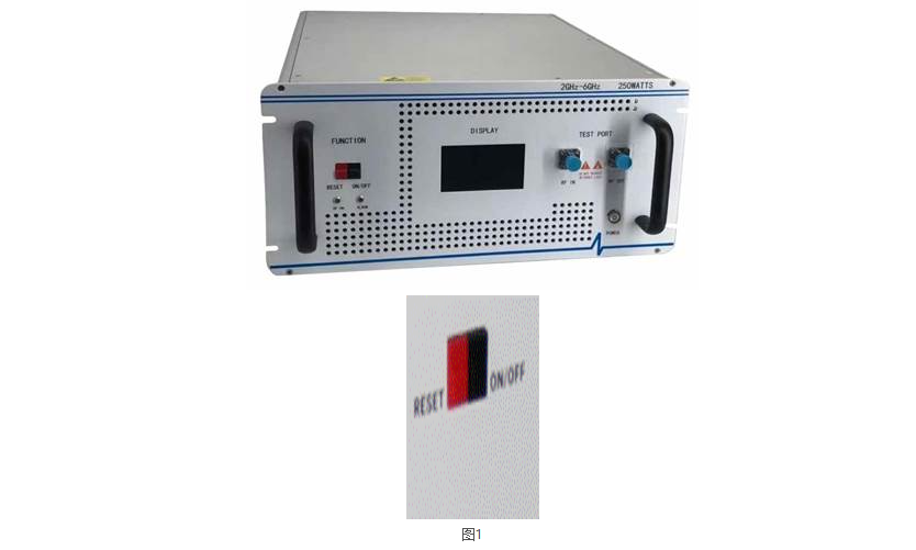
1)Front Panel Definition (See Figure 1)
|
|
1) Front Panel Definition (See Figure 1)
(1) RFIN: RF signal input port
(2) RFOUT: RF signal output port
(3) DISPLAY: Displays operating status including drive level, output power, temperature, standing wave ratio, frequency band switching, etc.
(4) FUNCTION: RF control button, mainly for reset and RF on/off functions
RESET: Integrates two functions: reset and RF enable.
When the power amplifier is in standby initial state, pressing this button activates normal operation.
When the amplifier triggers protection due to drive overload, over-temperature or high standing wave ratio, pressing this button resets the unit to normal working status.
RF toggle function: Press during normal operation to disable RF output; press again to resume normal operation.
ON/OFF: RF output switch. Press once to stop amplifier output; press a second time to restart operation.
(5) POWER: Main power switch. Press to turn on power; press again to cut off power supply.
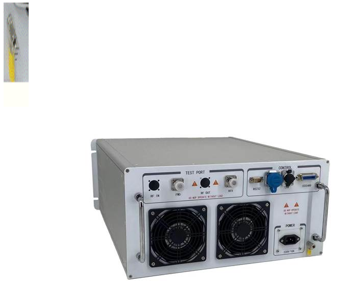
2) Rear Panel Definition (See Figure 2)
(1) RFIN: Spare RF signal input port
(2) RFOUT: Spare RF signal output port
(3) FWD: Forward coupled monitoring port
(4) REV: Reverse coupled monitoring port
(5) LAN: Ethernet / GPIB communication port
(6) AC220±10V: AC mains power socket
(7) Equipment grounding terminal |
|
|
| Note: The appearance and specifications of the product are subject to optimization and modification as our products are upgraded. The company reserves the right of final interpretation without prior notice. |
Complies with ISO 11452-2 and GB 33014.2 requirements
Operating Frequency: 80 MHz – 6 GHz
Output Power: 250 W – 2000 W
Input VSWR: ≤2.0
Output VSWR: 2.0 – 4.5
AC Operating Voltage: 198 V–240 V, 340 V–530 V
Operating Temperature: 0 ℃ – 40 ℃
Full Series of ISO 11452-2 Power Amplifiers
Suitable for automotive electronic field strength testing
User-friendly human-machine interface
Rational design with elegant appearance
Reliable quality and easy operation
Professional EMC Power Amplifier Solutions
|
|
I. Power Amplifier Series Models
|
|
Model
|
Frequency
MHz
|
Output Power
Min
(Past)
dBm
|
Output Power
Typ(P-1)
dBm
|
Gain
Min
dB
|
Flatness
Typ
dB
|
Output VSWR
Typ
|
Input VSWR
Typ
|
Dimension
L*W*Hmm*mm*mm
|
|
ZLPA80M1G1000
|
80-200
|
60.0
|
57.0
|
60.0
|
±2.0
|
5.0
|
2.0
|
480*550*1100
|
|
200-1000
|
57.0
|
54.0
|
57.0
|
±3.0
|
5.0
|
2.0
|
|
ZLPA1G6G200
|
1000-6000
|
53.0
|
50.0
|
53.0
|
±4.5
|
4.0
|
2.0
|
480*550*225
|
|
ZLSPDTDC6G2000-3
|
80-6000
|
63.0
|
---
|
---
|
±1.0
|
---
|
2.0
|
480*550*225
|
|
|
|
|
II.Technical Specifications
|
|
|
|
1、Model:LDPA80M1G1000/500
|
|
|
|
Operating Specifications(Technical Specifications
|
|
Parameter(Parameters)
|
Min
|
Typ
|
Max
|
Units(单位)
|
|
Frequency(Frequency)
|
80.0
|
---
|
200.0
|
MHz
|
|
200.0
|
---
|
1000.0
|
|
Avg Output PowerPast(Output Saturation Power)
|
1000.0
|
---
|
---
|
Watts
|
|
500.0
|
---
|
---
|
|
Avg Output Power P-1(Output Linear Power)
|
500.0
|
---
|
---
|
Watts
|
|
400.0
|
---
|
---
|
|
Gain(Gain)
|
60.0
|
---
|
---
|
dB
|
|
57.0
|
---
|
---
|
|
Power In(Input Power)
|
---
|
---
|
3
|
dBm
|
|
Supply Voltage(Supply Voltage AC)
|
340
|
---
|
530
|
V
|
|
Supply Power(Supply Power AC)
|
---
|
---
|
10000
|
W
|
|
Gain Flatness(Gain Flatnes)
|
---
|
±4.0
|
---
|
dB
|
|
Harmonic(Second Harmonic)@P1dB
|
---
|
-20
|
---
|
dBc
|
|
Spurious(Spurious)
|
---
|
-50
|
---
|
dBc
|
|
Storage Temp(Storage Temperature)
|
-20
|
---
|
60
|
℃
|
|
Case Oper Temp(Operation Temperature)
|
0
|
---
|
40
|
℃
|
|
Input VSWR(Input VSWR)
|
---
|
2.0
|
---
|
|
|
Output VSWR(Output VSWR)
|
---
|
5.0
|
---
|
|
|
Nominal impedance(Nominal Impedance)
|
---
|
50
|
---
|
Ω
|
|
Amplifier Safeguard Temp(Power Amplifier Temperature Protection)
|
60
|
---
|
---
|
℃
|
|
Safeguard Power In(InputSignal Protection)
|
---
|
---
|
3
|
dBm
|
|
Connector(Connector)
|
RFin:N-F,RFout:7/16-F,FWD:N-F,RVE:N-F(Connector on the Rear Panel)
|
|
Dimension(Dimension)
|
25U19 inch Chassis Approximately(480×550×1100mm)
|
|
Control system(Control)
|
Ethernet Port/GPIB
|
|
Remarks(Remarks)
|
|
|
|
|
|
|
|
2、Model:LDPA1G6G200
|
|
|
|
Operating Specifications(Technical Specifications)
|
|
Parameter(Parameters)
|
Min
|
Typ
|
Max
|
Units(单位)
|
|
Frequency(Frequency)
|
1.0
|
---
|
6.0
|
GHz
|
|
Avg Output PowerPast(Output Saturation Power)
|
200.0
|
---
|
---
|
Watts
|
|
Avg Output Power P-1(Output Linear Power)
|
80.0
|
---
|
---
|
Watts
|
|
Gain(Gain)
|
53.0
|
---
|
---
|
dB
|
|
Power In(Input Power)
|
---
|
---
|
3
|
dBm
|
|
Supply Voltage(Supply Voltage AC)
|
198
|
---
|
240
|
V
|
|
Supply Power(Supply Power AC)
|
---
|
---
|
3200
|
W
|
|
Gain Flatness(Gain Flatnes)
|
---
|
±4.5
|
---
|
dB
|
|
Harmonic(Second Harmonic)@P1dB
|
---
|
-20
|
---
|
dBc
|
|
Spurious(Spurious)
|
---
|
-50
|
---
|
dBc
|
|
Storage Temp(Storage Temperature)
|
-20
|
---
|
60
|
℃
|
|
Case Oper Temp(Operation Temperature)
|
0
|
---
|
40
|
℃
|
|
Input VSWR(Input VSWR)
|
---
|
2.0
|
---
|
|
|
Output VSWR(Output VSWR)
|
---
|
4.0
|
---
|
|
|
Nominal impedance(Nominal Impedance)
|
---
|
50
|
---
|
Ω
|
|
Amplifier Safeguard Temp(Power Amplifier Temperature Protection)
|
60
|
---
|
---
|
℃
|
|
Safeguard Power In(InputSignal Protection)
|
---
|
---
|
3
|
dBm
|
|
Connector(Connector)
|
RFin:N-F,RFout:N-F,FWD:N-F,RVE:N-F(Connector on the Rear Panel)
|
|
Dimension(Dimension)
|
5U19 inch Chassis Approximately(480×550×440mm)
|
|
Control system(Control)
|
Ethernet Port/GPIB
|
|
Remarks(Remarks)
|
|
|
|
|
|
III.Optional accessories
|
|
|
|
Option
|
Description
|
Paid
|
Option
|
Remarks
|
|
+A
|
Input and output interfaces are on the front panel.
|
Standard configuration
|
|
|
|
+B
|
Input and output interfaces are on the rear panel.
|
Standard configuration
|
|
Rear panel by default
|
|
+C
|
Security lock(dB15)
|
Standard configuration
|
|
|
|
+D
|
Provide forward and reverse coupling ports.
|
Optional at extra cost
|
|
|
|
+E
|
Gain,Adjustable power
|
Optional at extra cost
|
|
|
|
+F
|
Communication ports are optional.:Ethernet Port,GPIB
|
Standard configuration
|
|
Ethernet Port
|
|
|
|
|
IV. Accessories
|
|
1)Front Panel Definition (See Figure 1)
|
|
|
1) Front Panel Definition (See Figure 1)
(1) RFIN: RF signal input port
(2) RFOUT: RF signal output port
(3) DISPLAY: Displays operating status including drive level, output power, temperature, standing wave ratio, frequency band switching, etc.
(4) FUNCTION: RF control button, mainly for reset and RF on/off functions
RESET: Integrates two functions: reset and RF enable.
When the power amplifier is in standby initial state, pressing this button activates normal operation.
When the amplifier triggers protection due to drive overload, over-temperature or high standing wave ratio, pressing this button resets the unit to normal working status.
RF toggle function: Press during normal operation to disable RF output; press again to resume normal operation.
ON/OFF: RF output switch. Press once to stop amplifier output; press a second time to restart operation.
(5) POWER: Main power switch. Press to turn on power; press again to cut off power supply.
2) Rear Panel Definition (See Figure 2)
(1) RFIN: Spare RF signal input port
(2) RFOUT: Spare RF signal output port
(3) FWD: Forward coupled monitoring port
(4) REV: Reverse coupled monitoring port
(5) LAN: Ethernet / GPIB communication port
(6) AC220±10V: AC mains power socket
(7) Equipment grounding terminal
|
|
|
|
Note: The appearance and specifications of the product are subject to optimization and modification as our products are upgraded. The company reserves the right of final interpretation without prior notice.
|



 沪公网安备31012002002345号